
- Replacing a selenium rectifier with a silicon diode install#
- Replacing a selenium rectifier with a silicon diode full#
- Replacing a selenium rectifier with a silicon diode series#
current required from the rectifier / diode the capacity of the reservoir capacitor / condenser that follows it - amongst others.Ī bridge rectifier will use both excursions of the incoming AC voltage, called full wave rectification. The value of this resistor will depend on many variables, e.g.
Replacing a selenium rectifier with a silicon diode series#
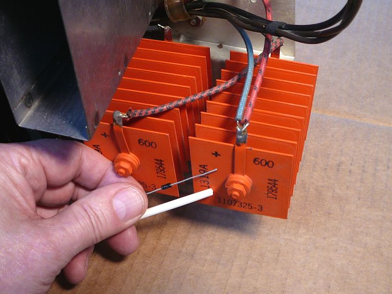
You are correct in anticipating that a series resistor may be required when a selenium rectifier is replaced with a silicon diode the former has a much higher forward resistance than the latter. There isn't a corresponding word in English to correspond to 'diode' - e.g. current (albeit a pulsating current if this current then passes into a resistance) is called 'rectification' - and the device that performs this is therefore known as a 'rectifier'. I suspect your confusion stems from the English. The process of converting a bi-polarity current into an omni-directional current is performed by each, of course. So, in summary, if you're comfortable with the basic theory of the operation of a 'diode' - then you know what you need to know about a 'rectifier' - be this a solid-state or a vacuum device. Both are 2-terminal devices if the term 'rectifier' is being used to refer to a ' bridge rectifier', then omitting the adjective 'bridge' is wrong and misleading. Generally, the terms 'rectifier' and 'diode' are synonymous, although there is a tendency to prefer the word 'diode' for low-power and 'rectifier' for high-power applications. If it is an AC/DC set without a mains transformer, you'll need a surge protecting resistor. That's okay as long as it has a mains transformer.
Replacing a selenium rectifier with a silicon diode install#
In the case of the Grundig, it was only 10 volts above what was stated on the schematic, so I decided not to install a dropping resistor. I then calculate the voltage drop needed to get it back down to the nominal voltage. I have installed the new ones, turned the set on and let it warm up, and then measure the current and voltage of the HT (B+ in your case). Modern silicon bridges have less voltage drop across the diodes than selenium ones. Going to half wave rectification will increase the hum. If your set had a bridge, then the capacitors were designed for that. Using only a single diode in place of a bridge will require the filter capacitors to store enough energy on positive going excursion to last until the next positive going excursion (nearly 34 ms in your case). A single diode will only use one half of the incoming AC, hence it's called half wave rectification.

So your 60 Hz incoming AC will be 120 Hz pulsed DC at the output of the bridge. A bridge rectifier on a schematic will be shown as 4 diodes.Ī bridge rectifier will use both excursions of the incoming AC voltage, called full wave rectification. I haven't heard of anyone replacing a selenium bridge with a single diode. Some folks gut the selenium bridge rectifiers and stuff it with 4 modern silicon diodes and capacitors to keep the same look as before.

Of the two radios I've worked on with selenium bridge rectifiers (a Grundig and a Telefunken), I've replaced the bridge with silicon bridge rectifiers. My first radios are the kind with out transformers. I plan on getting an ISOLATION transformer and VARIAC to ramp up to safely assure my voltages are OK. I understand that I will need a drop down resistor because of the silicon diodes lower fwd voltage drop. It's clear I don't want a Selenium Diode in my new old radios. I plan on buying some radios, re-cap them, check replace resistors and the SELENIUM DIODE. I know enough about electronics to know to ASK.

I have a working knowlege of DC electronics and some RF and audio circuits, but new to tube radios. It looks like it drives the filaments of the tubes? So one diode clips the AC wave to keep it from being noisy? I AM GUESSING? HELP! I noticed in schematics for old radios they call Capacitors, Condensers. I think it is a term thing I am confused about "Rectifier". I understand it is advantageous to replace the Selenium RECTIFIER which a single Diode (not a rectifier Bridge).


 0 kommentar(er)
